This scenario plays out daily across manufacturing facilities that rely on reactive discovery. The fix isn't faster reaction. It's eliminating the discovery gap entirely by monitoring equipment signals continuously and alerting teams to developing problems before failures occur.
This article covers which signals to monitor, how alert pipelines work, how to design alert rules that actually fire when they should, and how to connect alerts to shop floor workflows so teams can act — not just know.
Key Takeaways
- Vibration, temperature, motor current, cycle time, and coolant pressure are the highest-value monitoring signals.
- Tiered thresholds (warning vs. critical) prevent alert floods while ensuring genuine faults get immediate attention.
- Alert fatigue kills monitoring programs; tune your thresholds within the first 90 days.
- Plan the detection-to-action response cycle before any alert goes live.
- NIST research links high reactive-maintenance reliance to 3.3x more downtime than facilities using advanced maintenance approaches.
Why Equipment Breakdowns Cost More Than You Think
The immediate cost of a breakdown — the repair itself — is usually the smallest part of the bill. What actually hurts is everything around it.
A single unplanned stoppage triggers a cascade of costs that extend well beyond the repair invoice:
- Lost production while the machine sits idle
- Scrap from parts mid-cycle when the fault hit
- Missed delivery commitments
- Emergency labor rates for technicians called in after hours
- Expedited freight for parts that weren't stocked
According to a Siemens/Senseye manufacturing downtime study, a single lost production hour costs more than $2 million in automotive manufacturing, and the average large facility loses 25 hours per month to unplanned downtime.
The Discovery Gap
The discovery gap is the time between when a fault begins developing and when it's detected. In reactive environments, that gap closes only when something visibly fails — a machine stops, an operator hears an unusual noise, or a quality check catches defective parts.
Compare that to condition-based monitoring: vibration signatures, thermal readings, and current draws often shift measurably before a fault becomes a failure. The earlier a developing problem surfaces, the more options teams have — schedule a repair during a planned break, swap a component before it fails, or at least stage parts and personnel before the machine goes down.
Three Maintenance Approaches
| Approach | Trigger | Typical Outcome |
|---|---|---|
| Reactive | Machine failure | Longest downtime, highest total cost |
| Preventive | Calendar schedule | Planned but sometimes unnecessary |
| Condition-based | Actual equipment state | Lowest unplanned downtime, best ROI |
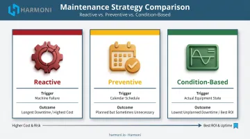
Real-time alerting is the operational foundation of condition-based maintenance. The sections that follow cover how to set those alerts up — from selecting the right data sources to defining thresholds that catch real problems without flooding teams with noise.
Which Equipment Signals Should You Monitor in Real Time?
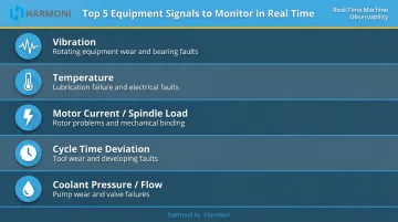
Not all signals are equal. These five are the most actionable for manufacturing equipment:
- Vibration — rotating equipment wear, imbalance, and bearing faults
- Temperature — lubrication failure, friction, and electrical faults
- Motor current / spindle load — rotor problems, mechanical binding, and tool wear
- Cycle time deviation — tool degradation, material inconsistency, or developing faults
- Coolant pressure and flow — pump wear, filter blockages, and valve failures
Vibration
The most widely used signal for rotating equipment — motors, spindles, pumps, gearboxes. Rising vibration amplitude or shifting frequency signatures indicate bearing wear, imbalance, misalignment, or looseness. ISO 13373-1 provides the foundational guidelines for vibration data collection in condition monitoring, covering transducer selection, attachment, and signal conditioning.
Vibration shifts are often detectable days or weeks before failure — enough lead time for a planned repair rather than an emergency stoppage.
Temperature
Abnormal temperature rise — particularly without a corresponding load change — signals lubrication failure, increased friction, or electrical faults. This applies across motors, bearings, hydraulic systems, and cutting zones. Thermal sensors and infrared approaches both work; the key is having a baseline to compare against.
For hydraulic systems specifically, oil life halves for every 15°F above the 140°F ceiling — making temperature one of the most cost-sensitive signals to watch.
Motor Current and Spindle Load
Gradual increases in current draw can indicate rotor problems, overloading, or mechanical binding — often before any physical symptom appears. This is especially useful for machines where attaching physical sensors isn't practical.
In CNC environments, spindle load is a direct proxy for tool wear. As a cutting tool degrades, the spindle works harder to maintain the same cut — a signal that's already available through the machine controller without additional hardware.
Cycle Time Deviation
A machine consistently finishing cycles faster or slower than its established baseline is telling you something. Causes include tool wear, material inconsistency, or a developing mechanical problem. Cycle time data is typically available through CNC controllers and machine monitoring systems — no additional sensors required.
Coolant Pressure and Flow
Pressure drops or flow anomalies in hydraulic and coolant circuits signal pump wear, filter blockages, or valve failures. These failures tend to appear gradual — then turn into unplanned downtime, scrapped parts, and coolant loss all at once. Catching pressure deviation early is one of the fastest ways to close that gap.
How a Real-Time Equipment Alert System Works
Sensors and Data Acquisition
Physical sensors — accelerometers, thermal sensors, current clamps, pressure transducers — attach to equipment and sample signals continuously. For modern CNC machines, a significant portion of this data is already available without additional hardware.
Controllers from Haas, Fanuc, Mazak, Siemens, and Heidenhain expose internal data streams — spindle load, axis current, alarms, cycle state — through protocols like MTConnect, OPC UA, and manufacturer-specific interfaces (FOCAS for Fanuc, Q commands for Haas NGC). Platforms like Harmoni connect directly to these controllers across all major brands, pulling native machine data without requiring machine replacement or significant hardware investment.
For legacy equipment where controller data access is limited, analog inputs and current sensors can determine machine state and feed that data into the same monitoring pipeline.
Connectivity and Analytics Layer
Processed data travels to a central analytics platform via industrial networking — wired Ethernet, Wi-Fi, or cellular. The analytics layer aggregates data across all monitored machines, applies baseline models, and runs anomaly detection to flag developing faults before they become failures — comparing current readings against historical baselines to distinguish normal variation from a fault in progress.
Edge processing matters here too. Processing data close to the machine delivers three concrete benefits:
- Reduces network load by filtering and compressing signals before transmission
- Enables fast local alerts the moment a reading goes out of range
- Keeps monitoring active during connectivity interruptions
Alert Delivery and Workflow Integration
Detecting an anomaly means nothing if that signal doesn't reach someone who can act on it — quickly and through a channel they actually monitor.
Effective alert delivery combines:
- Dashboards visible to production supervisors from any device
- Machine-side displays at the operator terminal
- Exception alerts pushed directly to managers with context
- Visual Factory indicators that communicate machine status across the floor without requiring anyone to check a screen
Harmoni's platform, for example, surfaces exception alerts to managers who can contact work cells directly, while machine-side command centers keep operators informed without requiring them to leave their station or check a separate system.
Designing Effective Alert Rules for Manufacturing Equipment
Threshold-Based Alerts
Threshold alerts fire when a parameter crosses a predefined limit. They're fast to implement and easy for operators to understand.
Concrete examples:
- Spindle load exceeds 85% of rated capacity for more than 10 consecutive seconds
- Bearing temperature rises above 180°F
- Vibration RMS exceeds the established baseline by 25%
Critical rule: thresholds must be set from actual machine baselines, not generic defaults. A threshold calibrated to a different machine type, operating environment, or material will generate either constant false positives or miss real faults entirely.
Tiered Severity Levels
Every alert system needs at least two tiers:
| Tier | Trigger | Response |
|---|---|---|
| Warning | Approaching the limit | Log it, investigate at next opportunity |
| Critical | Limit exceeded | Immediate action — stop or dispatch maintenance now |
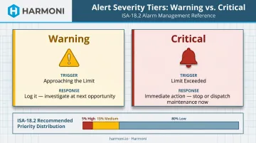
ISA-18.2 alarm management guidance recommends a priority distribution of roughly 5% high, 15% medium, and 80% low. Stack too many high-priority alerts and operators stop treating any of them as urgent.
Anomaly Detection Alerts
Anomaly-based alerts detect deviations from established baseline behavior without requiring a predefined limit. The benefit: catching failure modes that don't follow predictable patterns.
Both statistical approaches (moving average comparisons, standard deviation analysis) and machine learning models trained on historical data fall in this category.
| Approach | Strengths | Watch Out For |
|---|---|---|
| Threshold alerts | Simple, fast to implement, easy to explain | Misses faults that don't cross a fixed limit |
| Anomaly detection | Catches subtler failure patterns | Requires historical data; more false positives early on |
A practical approach: start with threshold alerts on the highest-consequence parameters. Layer in anomaly detection as data accumulates and baselines solidify.
Context-Rich Alert Design
An alert that reads "vibration high on Machine 4" tells a maintenance tech almost nothing useful. They still have to find out what's running, what the current reading is relative to normal, and where to start looking.
Useful alert context includes:
- Which machine and which parameter
- Current reading vs. established baseline
- Which job is running and which operator is at the machine
- Recommended next action
Alerts stripped of context slow response. The goal is to hand the tech everything they need to act immediately — no information-gathering required before work can begin.
How to Prevent Alert Fatigue on the Shop Floor
Alert fatigue happens when teams receive too many notifications — especially low-priority or false ones — and start ignoring all of them, including the critical ones.
This is one of the most common ways real-time alerting programs fail in practice. ISA-18.2 benchmarks suggest 1 alarm per 10 minutes is about the limit of what an operator can handle without it affecting other duties. Exceed that consistently and the notifications become background noise.
Practical strategies to reduce alert fatigue:
- Set thresholds from real baselines, not conservative guesses — the single biggest source of nuisance alarms
- Suppress duplicate alerts within defined time windows (don't fire the same alert every 30 seconds while a fault persists)
- Route low-priority alerts to shift logs rather than individual notifications — supervisors review them at the next opportunity
- Require acknowledgment before escalating an alert to the next responder
- Review and refine alert rules on a regular schedule — especially in the first 90 days
The first three months of any monitoring program will surface which alerts are actionable and which generate noise. Tuning rules based on that feedback is how the system earns operator trust — and how it stays useful over time.
Closing the Loop: From Alert to Action
An alert is only as valuable as the response it triggers. Without a defined response process, teams improvise under pressure — and that's when critical steps get skipped.
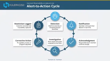
Define the complete cycle before alerts go live:
- Detection — signal exceeds threshold or baseline deviation identified
- Notification — right person receives alert with full context
- Acknowledgment — someone owns the alert; escalation clock stops
- Investigation — tech goes to the machine, assesses the flagged parameter
- Corrective action — decision to continue, schedule, or stop; action executed
- Resolution logged — outcome recorded for future baseline refinement
ERP and MES Integration
The response cycle shortens when alert data connects to work order systems. A triggered fault that automatically generates a maintenance work order (with machine ID, fault type, severity, and current job context pre-populated) eliminates a manual handoff that often causes delays.
Harmoni's factory orchestration platform sits between machines, ERP systems, and operators, combining machine data with ERP job context and operator activity in one unified view. When an equipment signal fires, maintenance and production teams can see which machine, which job is at risk, and what the production impact is — without piecing that information together from separate systems.
What Good Looks Like Over Time
A well-functioning alert system changes the maintenance profile of a facility. NIST research shows predictive maintenance cuts downtime by 15% compared to preventive maintenance — and by 3.3x compared to reactive-maintenance-heavy operations. The data record built from months of monitoring makes future baselines more accurate and thresholds better calibrated, building on itself as the system matures.
Frequently Asked Questions
Which monitoring data types are best for real-time alerting?
Vibration is the primary signal for rotating machinery, temperature covers thermal and lubrication faults, and motor/spindle current reveals electrical and mechanical loading issues. Cycle time deviation is especially actionable in CNC environments. The best starting point depends on which failure modes carry the highest cost for your specific operation.
What should I look for in a real-time equipment monitoring tool?
Look for machine-native data connectivity (direct CNC controller integration without added hardware), tiered alert severity with suppression logic, and integration with ERP or work order systems. Platforms that connect alerts directly to maintenance workflows , rather than requiring manual follow-up, deliver the fastest response and the lowest alert overhead.
What is the difference between threshold-based and anomaly-based equipment alerts?
Threshold alerts fire when a parameter crosses a predefined limit — fast to implement and easy to explain to operators. Anomaly detection identifies deviations from behavioral baselines, catching subtler developing faults but requiring historical data and often generating more false positives early on.
How do you prevent alert fatigue on the shop floor?
Set thresholds from actual machine baselines rather than defaults, use severity tiers to route low-priority alerts to logs, and suppress duplicates within defined time windows. Review all alert rules within the first 90 days — most nuisance alarms come from thresholds that were never calibrated to real operating conditions.
How do real-time equipment alerts integrate with ERP and MES systems?
Alerts should connect to work order systems so a triggered fault automatically creates a maintenance task with equipment, severity, and job context pre-populated. Platforms that act as an orchestration layer between machines and ERP make this more reliable than point solutions that require manual bridging, reducing data entry burden on maintenance staff.
What happens between detecting an equipment alert and preventing a breakdown?
Acknowledge the alert, investigate the flagged parameter at the machine, decide whether to continue or stop for maintenance, then execute and log the corrective action. Document and rehearse this process before alerts go live. Consistent responses prevent the improvisation that leads to missed steps and extended downtime.